Hi,
Gentlemen beautiful builds everyone.
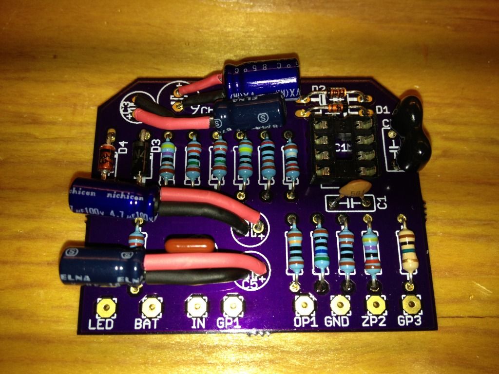
If switch pops then C5 could be leaky- measure voltage at footswitch relative ground.
Identify wires to points on board GP1,GP2,GP3 and verify that those are correct and there should be zero volts at GP1,GP2 and GP3 on the footswitch and on the board.
Note modern electrolytic capacitors do not take well to reverse voltage and may be damaged at less than a few percent reverse voltage visa vi Working voltage marking.
Some may remember making fireworks of Elkos and a battery........however modern capacitors like this can develop similar behavior as tantalum capacitors when those break and you can get a semiconductor joint e.g. a zener function or resistor or a combination.
Anyway it happens that electrolytics have a leakage current that is high enough to cause a pop and therefore one can limit R1 to 510K or 470K
Some 30 years ago in design one could actually count on the reverse voltage as percentage of
of stamped value Working voltage and you could find it in the data sheet of the relevant capacitor .

OK effect of OZ control vary greatly and can be very important with some fuzz designs ( if one would like to experiment with sound) but also when trying out cables for pedal boards there's a realtime experiment. It is not meant to be a drastic control but on some pedalboards I have seen built that I helped have fault finded I would have found use for both of these controls to make sound about the same bypass as through the pedalboard....desirable it would seem....
Voltage that CB can handle is easily 18V if Working Voltage on capacitors are the same as in schematic and you could run the IC at 36V if all capacitors are 50V types but be ware that higher output swing than 7V peak can be damaging to many amplifiers and accessories and this was a problem in some set ups back in the late 70's: musicians pumping to high voltage into amplifier inputs- Only try this if you can determine the safe input voltage the amplifier input can take
Have great fun

BJ
 Viewed 1831 times")
 Viewed 1831 times")
 Viewed 1831 times")
 Viewed 1831 times")
