The Folk Buffer.
Moderator: Moderators
30 posts
• Page 1 of 3 • 1, 2, 3
The Folk Buffer.
![]() by jfromel » Sat May 23, 2009 2:28 am
by jfromel » Sat May 23, 2009 2:28 am
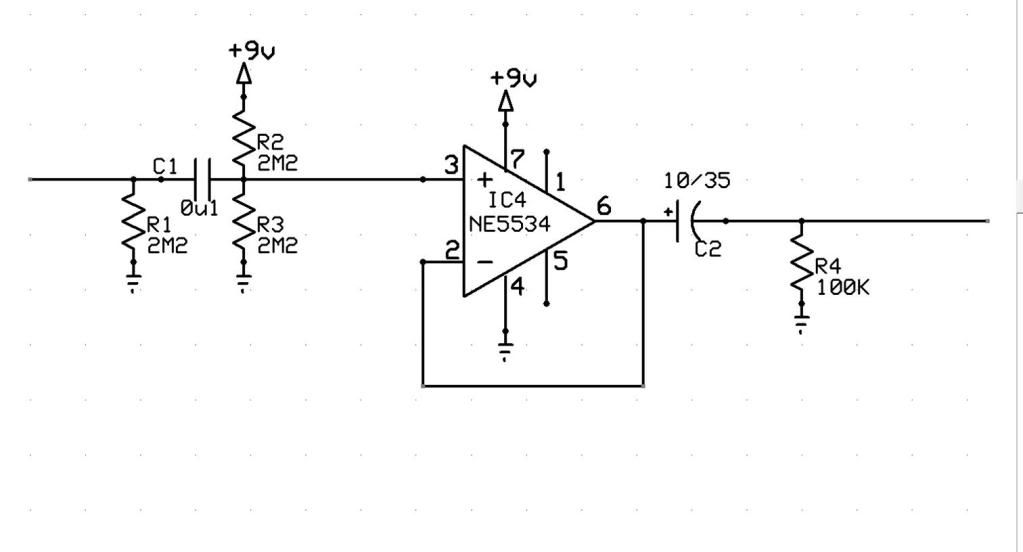
Bjorn and I have been talking about the usefulness of buffers, not nearly as flashy or sexy as an OD or Fuzz but can really have their place. So I thought I would post the buffer section out of my Shape EQ, it's not rocket science, just a good buffer. should be easy enough to build on pad per hole or Vero and cost less than $10 to home brew. The buffer has been a huge hit on my EQ and I am thinking about adding it as an option to some of my other pedals like the compressor and boost.
Part time pedal builder with a day job now with a web site http://www.fromelelectronics.com
- jfromel
- Posts: 201
- Joined: Sun Aug 10, 2008 3:02 pm
- mills
- Posts: 145
- Joined: Thu Apr 24, 2008 10:28 pm
- Location: Canada
- Guitars:: Fender P/J Bass, Fender strat/tele hybrid
- amps: 5e3 clone, solidstate bass head
- pedals: 20
Re: The Folk Buffer.
![]() by BJF » Thu Jun 11, 2009 3:48 pm
by BJF » Thu Jun 11, 2009 3:48 pm
http://i213.photobucket.com/albums/cc43 ... Buffer.jpg
Hi,
I'll add a few ideas here.
Firstly for variable inputimpedance the purpose of which will be explained seperately, R1 can be made with a 47K resistor wired in series with a 2M linear trimmer or logaritmic potentiometer wired as variable resistor; for powersupply rejection ratio increase R2 can be made with two resistors from B+ 200K inseries with 1M8 and at junction of those bypass cap at 100nF can be connected to ground- this bypasses any disturbances in the B+ line; to protect input of OP amp at powerdown a resistor of 1K Ohm can be connected instead of a straight line from input bias divider to noninverting input ( marked + in the OP amp symbol) and/or further to reduce discharge current from capacitor C1 to safe level at powerdown the value can be choosen to 47nF; to reduce widebandnoise of OP-amp and to ensure unitygain stability a capacitor of 100pF can be connected between pins 5 and 8 of the NE5534A capsule; to protect output from backward discharge and shortcircuit and also make variable outputimpedance a trimmer or potentiometer wired as variable resistor in series with a resistor of 100 Ohms to 560 Ohms can be connected in series with output after R4 and then current is limited either driving a current input amplifier and output protected against discharge of output capacitor at shortcircuit; to protect output one 1N4148 switchingdiode can be connected directly at pin 6 with anodefacing ground and cathode facing pin 6 and also a 1N4148 switchingdiode connected with cathode facing B+ and anode facing pin 6 which then at powerdown ensures that voltage forced backwards into the output of amplifier cannot take on higher potential than the forward drop of the switching diodes regardless of polarity- safety measures like this are advisable when input and outputs are lead out ibnto the real world............to make sure that reversepower cannot develop across terminals 4 and 7 a series diode type 1N400X series rectifier diode then with anode facing DC-input and the cathode facing pin 7 and the bias network.
There would be no specific need for a bypass capacitor across the terminals 4 and 7 since powersupplyrejectionratio is very high inside the chip for high frequency decoupling a 100nF film capacitor can be connected while there should be no trouble with high frequency instability or disturbances if the compensation capacitor mentioned above of 100pF is connected across pins 5 and 8.
As a standalone buffer this circuit would then be protected for most common failure mechanisms and have variable input and outputimpedance.
It would of course be most great if this could be made in a metalbox that could fit say beneath a pedaltrain.......and this should be possible.
Short on variable outputimpedance and purpose thereof:
This can be used to set limits to fuzz with some fuzzpedals and it can also be used as a filter for disturbances outside the audioband inconjuction with 'ghost'capacitances in cables and connectors and thereby making systems quieter.
Purpose of variable inputimpedance can be used to tame resonance in guitar pick ups see thread on 'when is a buffer needed?'
Have fun
BJ
-

BJF - Posts: 522
- Joined: Tue Feb 27, 2007 4:43 am
- Location: Stockholm
- Guitars:: Les Pauls, V with P-90's and humbuckers, strats,tele duo-jet and expanding; pick ups mostly Lundgren or BJF/ Lundgren
Danelectro Barython - amps: MP CS-40, MP101, Hiwatt Custom 200, Hiwatt Custom 100, VOX AC15
Fender Blues De Ville, Fender Super Reverb, Marshall 5150 through various speakers - pedals: 42
Re: The Folk Buffer.
![]() by soulsonic » Fri Jun 12, 2009 2:59 am
by soulsonic » Fri Jun 12, 2009 2:59 am
You could use a bipolar supply with an offset trim, then you could possibly do without the output coupling cap. At the very least, it gives much greater headroom and lower noise.
I've done A/B/Y boxes with buffers run on bipolar supplies, and they sounded great.
I've done A/B/Y boxes with buffers run on bipolar supplies, and they sounded great.
-

soulsonic - Posts: 57
- Joined: Tue Mar 17, 2009 12:46 am
- Location: Circus Capital of the World!
Re: The Folk Buffer.
![]() by BJF » Fri Jun 12, 2009 5:03 pm
by BJF » Fri Jun 12, 2009 5:03 pm
Hi,
Yes, indeed one could at great results, while bipolar supplies are somewhat a luxuary item rarely available- that is unless you build one yourself.
Sadly to most musicians powersupplies and wallwarts would give but one polarity or AC
Come to think of it if there's interest one could make a little project on how to make a bipolar supply out of a 6V AC wallwart?
This would be something that could be built without accessing leathal voltages and that would by design ignore primaryvoltages from the wall as a 6V AC wallwart can be found worldwide with all safety markings required in any area. Also some standard supplies have an AC outlet of 6- 9V's that could be used........hm....
Indeed I would say I would have a motive for suggesting a buffer like this to be of a size that would fit beneath a pedaltrain since this I could see uses for at the shop and it would be one application that could appeal to many that have pedal boards and easily powered by standard powersupplies used on pedalboards.
An interesting note here is that on a demoboard there were ten pedals all of them truebypass and cables used were of low capacitance yet with all pedals bypassed there was a capacitance of approximately 500pF across the poles as I recall and that only in the cables............now the cables themselves contributed less than 100pF of the total capacitance but the connectors contributed the rest! Now adding to this one cable to amplifier and one to guitar capacitive load would change significantly with all pedals off and the first pedal in chain on.........
Resistive load is ignored here as that cahnged from 1M Ohms all pedals off to 500K first pedal on.
What is surprising here is the capacitance measured in the bare connectors!
A buffer strategically placed in the system would be able to make load near constant at a desired level and make the lenght and type of cable used from pedalboard to amplifier more or less a matter of what would make the most mechanical sense.....
Anyway have fun and keep the fun flowing
Hey I see a Folk pedal board coming here
BJ
-
BJF - Posts: 522
- Joined: Tue Feb 27, 2007 4:43 am
- Location: Stockholm
- Guitars:: Les Pauls, V with P-90's and humbuckers, strats,tele duo-jet and expanding; pick ups mostly Lundgren or BJF/ Lundgren
Danelectro Barython - amps: MP CS-40, MP101, Hiwatt Custom 200, Hiwatt Custom 100, VOX AC15
Fender Blues De Ville, Fender Super Reverb, Marshall 5150 through various speakers - pedals: 42
Re: The Folk Buffer.
![]() by jfromel » Mon Jun 22, 2009 11:51 pm
by jfromel » Mon Jun 22, 2009 11:51 pm
I have never worked with bi-polar supplies before anyhow Bjorn asked me to mock up the schem based on his comments
Corrected - changed D1, added input/output, changed c3 to 100p
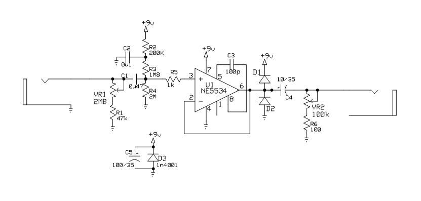
Corrected - changed D1, added input/output, changed c3 to 100p
Last edited by jfromel on Tue Jun 23, 2009 9:16 pm, edited 1 time in total.
Part time pedal builder with a day job now with a web site http://www.fromelelectronics.com
- jfromel
- Posts: 201
- Joined: Sun Aug 10, 2008 3:02 pm
Re: The Folk Buffer.
![]() by soulsonic » Tue Jun 23, 2009 2:26 am
by soulsonic » Tue Jun 23, 2009 2:26 am
Okay, I read through Björn's post again and I see that's how he said to connect it, but it still looks backwards to me from how I've see that sort of thing arranged.
Anyway, bipolar power for things like this are extremely simple and cheap to do with voltage inverter chips like the MAX1044. These chips take a positive voltage and use a capacitor charge pump circuit to make a negative voltage output. I use these all the time in several of my designs, and they are very handy and solve lots of problems. I've used the Microchip Tech. brand TC1044 chip in my Four Banger and they've proven to be very reliable - even in one unit which got damaged by incorrect power, the '1044 was still fine (my protection circuit helped, too).
Here is how I would do a simple buffer like this using a bipolar supply. When you use a bipolar supply, you don't need to make an artificial earth with a bias circuit.
The 47 ohm resistor in tandem with the 9v Zener diode protects the 1044 from damage from over-voltage, reverse voltage, and static discharge. Basically, the resistor and zener form a basic voltage regulator; if the voltage goes over 9v, the zener turns on and starts pulling current through the resistor until the voltage drops to 9v.
I think that having a variable resistance in series with the input of an inverting opamp is the most efficient way to give a variable input impedance, so that's how I've done it here. The input cap is large enough that you should get a full range response even at low impedance settings. The 2M2 input pulldown can be omitted if the buffer is the first thing in the signal chain.
Since I want the buffer to keep the same polarity as the input, I included a second inverting stage to flip the polarity back to what it was originally; this also gives us the opportunity to give a little extra gain to make up for any losses from the first stage and also allow for a little extra boost if wanted.
Using a 470k pulldown on the output means I can easily get away with using a 1uF output cap and still get a full low-frequency range. Since it's 1uF, I can use a film cap instead of an electrolytic and have better fidelity because of this.
The 22k resistor in series with the output is a little bonus that can help the buffer to sound better and more "natural" if it precedes an old-style fuzz.
So, that's my take on the whole buffer thing. I hope it makes sense... just throwing some possible ideas out there.
Anyway, bipolar power for things like this are extremely simple and cheap to do with voltage inverter chips like the MAX1044. These chips take a positive voltage and use a capacitor charge pump circuit to make a negative voltage output. I use these all the time in several of my designs, and they are very handy and solve lots of problems. I've used the Microchip Tech. brand TC1044 chip in my Four Banger and they've proven to be very reliable - even in one unit which got damaged by incorrect power, the '1044 was still fine (my protection circuit helped, too).
Here is how I would do a simple buffer like this using a bipolar supply. When you use a bipolar supply, you don't need to make an artificial earth with a bias circuit.
 Viewed 8557 times")
- simple buffer
 Viewed 8557 times")
The 47 ohm resistor in tandem with the 9v Zener diode protects the 1044 from damage from over-voltage, reverse voltage, and static discharge. Basically, the resistor and zener form a basic voltage regulator; if the voltage goes over 9v, the zener turns on and starts pulling current through the resistor until the voltage drops to 9v.
I think that having a variable resistance in series with the input of an inverting opamp is the most efficient way to give a variable input impedance, so that's how I've done it here. The input cap is large enough that you should get a full range response even at low impedance settings. The 2M2 input pulldown can be omitted if the buffer is the first thing in the signal chain.
Since I want the buffer to keep the same polarity as the input, I included a second inverting stage to flip the polarity back to what it was originally; this also gives us the opportunity to give a little extra gain to make up for any losses from the first stage and also allow for a little extra boost if wanted.
Using a 470k pulldown on the output means I can easily get away with using a 1uF output cap and still get a full low-frequency range. Since it's 1uF, I can use a film cap instead of an electrolytic and have better fidelity because of this.
The 22k resistor in series with the output is a little bonus that can help the buffer to sound better and more "natural" if it precedes an old-style fuzz.
So, that's my take on the whole buffer thing. I hope it makes sense... just throwing some possible ideas out there.
-
soulsonic - Posts: 57
- Joined: Tue Mar 17, 2009 12:46 am
- Location: Circus Capital of the World!
Re: The Folk Buffer.
![]() by jfromel » Tue Jun 23, 2009 9:18 pm
by jfromel » Tue Jun 23, 2009 9:18 pm
jfromel wrote:
Corrected - changed D1, added input/output, changed c3 to 100p
Part time pedal builder with a day job now with a web site http://www.fromelelectronics.com
- jfromel
- Posts: 201
- Joined: Sun Aug 10, 2008 3:02 pm
Re: The Folk Buffer.
![]() by BJF » Wed Jun 24, 2009 3:35 am
by BJF » Wed Jun 24, 2009 3:35 am
Hi,
Thanks Jfrommel for drawing this- I know pictures are easier to read than words and thanks for correcting my writing errors
Thanks Soulsonic for pointing out the faulty direction of one diode. I have corrected the whole post above.
I read at first through the post and as I had copied and pasted the directions - but alas forgot to change left right, right left, I just browsed through that part as the last part said.
".....which then at powerdown ensures that voltage forced backwards into the output of amplifier cannot take on higher potential than the forward drop of the switching diodes regardless of polarity-"
Siomething that holds the point, however my error and now corrected and its a good thing that it was brought up since when building this a reverse like this could accidentially be made
On variable output impedance I meant that looking from output at pin 6 you'd first have the E-lytic and after that on the negative side a 100K resistor to ground so that the negative side of the E-lytic is held at ground potential and then after that in series, i.e. from E-lytic negative via a resistor and a trimmer wired as a variable resistor.
Looking from output and back to pin 6 you'd enter a trimmer and resistor in series into the negtive side of Elytic and the positive side of the e-lytic going to pin 6. At the junction of elytic negative side and resistor there'd then be a 100K resistor to ground
The purpose of the 100K resistor is just to hold output at ground potential.
The purpose of the trimmer and resistor is to control the actual outputimpedance, which would be defined as looking from output back into pin 6 and internally in the chip and the internal impedance to ground would be on the order of a few Ohms.By placing this network of a resistor and a trimmer in series with signal and the internal outputimpedance the total output impedance can be effectively controlled.
The 100K resistor enters the outputimpedance equation in parallell and would have very small influence
Now having part of this 'inseries' impedance variable via a resistor an trimmer will do a couple of things like protect the output from short circuit; limit backward current during powerdown and if voltage is fed backwards into the output during power down.
Dynamically this series resistor and trimmer would set a limit if the buffer would drive a current input amplifier e.g. a Fuzz Face and it will form a variable part in the lowpassfilter that is created by capacitance in cables and contacts between poles and this series variable resistor will then control the upper cornerfrequency -3dB point- this will with the values choosen (560 Ohm's) be in most setups just above or at the outskirts of the audioband and its main porpose as a filter is to reduce wideband noise- at about 10K Ohms a noticable filter effect would occour.
to protect output from backward discharge and shortcircuit and also make variable outputimpedance a trimmer or potentiometer wired as variable resistor in series with a resistor of 100 Ohms to 560 Ohms can be connected in series with output after R4 and then current is limited either driving a current input amplifier and output protected against discharge of output capacitor at shortcircuit;
Have fun
BJ
-
BJF - Posts: 522
- Joined: Tue Feb 27, 2007 4:43 am
- Location: Stockholm
- Guitars:: Les Pauls, V with P-90's and humbuckers, strats,tele duo-jet and expanding; pick ups mostly Lundgren or BJF/ Lundgren
Danelectro Barython - amps: MP CS-40, MP101, Hiwatt Custom 200, Hiwatt Custom 100, VOX AC15
Fender Blues De Ville, Fender Super Reverb, Marshall 5150 through various speakers - pedals: 42
30 posts
• Page 1 of 3 • 1, 2, 3
Return to Folk Forum (DIY projects)
Who is online
Users browsing this forum: No registered users and 1 guest