The Folk Buffer.

A place for Do it Yourself projects

Moderator: Moderators

Re: The Folk Buffer.

Postby BJF » Wed Jun 24, 2009 3:43 pm

Hi,

Yes that's nifty solution using an integrated charge pump. Those are getting a bit less expensive these days I gather.

Very cool Soulsonic!
For large signal inputs such as even speaker outputs the inverting mode is excellent.

For low level signals noise gain is of consideration and it's one serious consideration in mixer amplifiers.
Noisegain is the amplification of the internal noisegenerators in the chip and is defined by the feedback network +1and can therefore at lowest be 1 time as in a noninverting buffer or an inverting amplifier with zero Ohm's feedback.

Here given three examples of noisegain:

A noninvertingbuffer:
Noisegain is then 1
An inverting buffer:
Noisegain is then 2 since then basic gain expression gives
R1/R2 when R1=R2 gives 1 and that added to 1 gives 2
A unitygain mixer:
Noisegain is R1/R2+1 but R2 is now defined by all input resistors parallelled while under unity gain for signals then gain per channel is R1/R2 per channel.
However noisegenerators inside will be amplified by under these conditions by R1/ ( R2x N) where N is the number of channels.
It follows that with ten inputs each at unity gain the noisegain will be 20dB.

With series amplifiers the noisegain adds on in dB's and so two in a row unity gain inverting amplifiers have a noise gain of 12dB.

Noisegain is the factor with which noise is amplified and not to be confused with the factor with which signals are amplified.

Further optimizing noise preformance of an NE5534A, which has lower noise factor than its dual sibling NE5532, it can be shown that lowest noise from result in noninverting mode when source impedance is between 5 and 10K approximately 6K8 ..

A guitarpick up has a DC resistans in the vincinity but the total impedance can be more than ten times at resonance- actually a guitarpick up is a troublesome source ;) and also the reason a buffer can be needed in the first place.

There are always trade offs:
With a dual inverting design inputs are protected at all times and it can handle large signalswings and it can be simple. And the Soulsonic design is a more orless bulletproof design that can take a lot of abuse. However noise could be lower.

Note that on higher supplies total distance to noise can be increased as larger signals can be handled also very few OP amps are designed to work at low voltages.
The NE5532 and NE5534A can both work down to 6V's or from a bipolar supply at 3V's each rail

In a noninverting design then noisepreformance can be optimized but at the same time a number of things need to be protected. Noise gain can then be 1 as opposed to 12dB's and generally noise preformance is better via the noninverting input. With proper protection a noninverting unitygain buffer can be made more or less bulletproof too.

Simple transistor buffers such as the common collector circuit as used in most guitarpedals gain is invariably lower than 1. See 'When is a Buffer needed?' thread on mnore on this.


Here's an interesting thing:
There's an early edition of japanese overdrives that have two dual OP amps and outof those four OP amps two are used as buffers. However the chips choosen have a bit high noisefigure and so simplifying this by changing the buffers to CK types then noise goes down but so does voltage amplification.........however since switching is electronic and the buffers active at all times then it makes little difference............or?
One can make a transitor buffer with with emitter output that has a gain of exactly 1 but it makes the emitterload a bit complicated and personally I have only seen that used once in a HiFi

Now it follows one can in a buffer pursue gain of one ( maybe a little more as is done in one once made in Japan Chorus that is quite famous); or one can try to get lowest noise and at any rate try the best to protect the circuit from failure; and or one can pursue getting the highest headroom or one can pursue making the lowest cost or most effective per cost.........

While there are many ways of optimizing even something like a buffer thinking about what would be good to optimize gives a greater understanding of the use oif buffers.

Oh and a very cool buffer with two outputs one in phase and one outof phase could result from this discussion.
Consider that being able to alter phase can be most useful in some effects systems:

There was a bassplayer at my shop a few weeks ago with a phase related problem and it could be solved by inserting an inverting buffer after one of his pedals.

Phaseangle becomes important when compared to another phaseangle.......

In bass systems effects can often be placed parallell so as not to loose the deep end ;)

Just some thoughts.

Have fun and carry on gentlemen
User avatar
BJF
 
Posts: 522
Joined: Tue Feb 27, 2007 4:43 am
Location: Stockholm
Guitars:: Les Pauls, V with P-90's and humbuckers, strats,tele duo-jet and expanding; pick ups mostly Lundgren or BJF/ Lundgren
Danelectro Barython
amps: MP CS-40, MP101, Hiwatt Custom 200, Hiwatt Custom 100, VOX AC15
Fender Blues De Ville, Fender Super Reverb, Marshall 5150 through various speakers
pedals: 42

Re: The Folk Buffer.

Postby ibodog » Fri Sep 11, 2009 10:22 am

I built up that Soulsonic buffer on protoboard but it does not pass signal when power is applied. I do get the correct voltages on pin 4 and pin 8 of the op amp. If I remove power the circuit does pass through a signal.

Anyone build the other buffer on breadboard or protoboard?
ibodog
 
Posts: 60
Joined: Thu May 14, 2009 9:25 am
Guitars:: Tele, Strat, Les Paul
amps: Fender, Vox, Stallion
pedals: 70

Re: The Folk Buffer.

Postby BJF » Sat Nov 07, 2009 7:15 pm

ibodog wrote:I built up that Soulsonic buffer on protoboard but it does not pass signal when power is applied. I do get the correct voltages on pin 4 and pin 8 of the op amp. If I remove power the circuit does pass through a signal.

Anyone build the other buffer on breadboard or protoboard?


Hi


If you built it exactly like in the picture then it won't work U1A needs a feedback resistor.
This may have fallen off the picture and I am sure Soulsonic will suggest a value.
You can try about 560K Ohms and that would make input trimmer set gain about 1 at center position

Have fun
BJ
User avatar
BJF
 
Posts: 522
Joined: Tue Feb 27, 2007 4:43 am
Location: Stockholm
Guitars:: Les Pauls, V with P-90's and humbuckers, strats,tele duo-jet and expanding; pick ups mostly Lundgren or BJF/ Lundgren
Danelectro Barython
amps: MP CS-40, MP101, Hiwatt Custom 200, Hiwatt Custom 100, VOX AC15
Fender Blues De Ville, Fender Super Reverb, Marshall 5150 through various speakers
pedals: 42

Re: The Folk Buffer.

Postby BJF » Sat Nov 07, 2009 7:19 pm

Hi,

There was also a discussion about making a folkbuffer as a kit, while first this may have to be revived and we'll see where it leads.

This thread linked contains answers I have given on buffer uses

viewtopic.php?f=3&t=868


Have fun
BJ
User avatar
BJF
 
Posts: 522
Joined: Tue Feb 27, 2007 4:43 am
Location: Stockholm
Guitars:: Les Pauls, V with P-90's and humbuckers, strats,tele duo-jet and expanding; pick ups mostly Lundgren or BJF/ Lundgren
Danelectro Barython
amps: MP CS-40, MP101, Hiwatt Custom 200, Hiwatt Custom 100, VOX AC15
Fender Blues De Ville, Fender Super Reverb, Marshall 5150 through various speakers
pedals: 42

Re: The Folk Buffer.

Postby soulsonic » Sun Nov 08, 2009 6:55 am

Yes, I made a mistake in the design. :oops:
I will try something new.
User avatar
soulsonic
 
Posts: 57
Joined: Tue Mar 17, 2009 12:46 am
Location: Circus Capital of the World!

Re: The Folk Buffer.

Postby ibodog » Sat Nov 21, 2009 1:26 pm

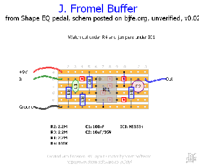
Here's the other buffers on vero.
Fromel Buffer Shape EQ unverified v0.02.gif

[modded buffer layout deleted - see later post for corrected one]
Last edited by ibodog on Tue Nov 24, 2009 12:08 am, edited 4 times in total.
ibodog
 
Posts: 60
Joined: Thu May 14, 2009 9:25 am
Guitars:: Tele, Strat, Les Paul
amps: Fender, Vox, Stallion
pedals: 70

Re: The Folk Buffer.

Postby BJF » Sat Nov 21, 2009 3:24 pm

ibodog wrote:Here's the other buffers on vero.
Fromel Buffer Shape EQ unverified v0.01.gif

Fromel Buffer with bjfe mods unverified v0.01.gif


Hi Ibodog,

Thank you! That's great that you took the time to do this!

Ah, it's been a long time since I made something on veroboard- actually I quickly shifted into vectorboard for various reasons :wink:

As far as I can see the layout is perfect and according to the schematic on page one this thread.
There's however a note I put on outputimpedance and I'll put that again here

The purpose of the 100K resistor is just to hold output at ground potential.
The purpose of the trimmer and resistor is to control the actual outputimpedance, which would be defined as looking from output back into pin 6 and internally in the chip and the internal impedance to ground would be on the order of a few Ohms.By placing this network of a resistor and a trimmer in series with signal and the internal outputimpedance the total output impedance can be effectively controlled.
The 100K resistor enters the outputimpedance equation in parallell and would have very small influence

Now having part of this 'inseries' impedance variable via a resistor an trimmer will do a couple of things like protect the output from short circuit; limit backward current during powerdown and if voltage is fed backwards into the output during power down.
Dynamically this series resistor and trimmer would set a limit if the buffer would drive a current input amplifier e.g. a Fuzz Face and it will form a variable part in the lowpassfilter that is created by capacitance in cables and contacts between poles and this series variable resistor will then control the upper cornerfrequency -3dB point- this will with the values choosen (560 Ohm's) be in most setups just above or at the outskirts of the audioband and its main porpose as a filter is to reduce wideband noise- at about 10K Ohms a noticable filter effect would occour.


to protect output from backward discharge and shortcircuit and also make variable outputimpedance a trimmer or potentiometer wired as variable resistor in series with a resistor of 100 Ohms to 560 Ohms can be connected in series with output after R4 and then current is limited either driving a current input amplifier and output protected against discharge of output capacitor at shortcircuit.


If then the ooutput section would be rearranged and value of VR2 would be made say 10K in series with 100 Ohms.
In words hooked up like this from negative end of C4 R6=100K goes to ground and also at same point 100 Ohms goes via VR2=10K to output.
Outputimpedance can be viewed as the impedance as seen from output looking back into the amplifier and for an OP amp the output impedance at gain = 1 is close to zero Ohms......and so what would be in series as we have now put a resistor and a trimmer would be a variable output impedance

Have fun
BJ
User avatar
BJF
 
Posts: 522
Joined: Tue Feb 27, 2007 4:43 am
Location: Stockholm
Guitars:: Les Pauls, V with P-90's and humbuckers, strats,tele duo-jet and expanding; pick ups mostly Lundgren or BJF/ Lundgren
Danelectro Barython
amps: MP CS-40, MP101, Hiwatt Custom 200, Hiwatt Custom 100, VOX AC15
Fender Blues De Ville, Fender Super Reverb, Marshall 5150 through various speakers
pedals: 42

Re: The Folk Buffer.

Postby Bobby D » Sat Nov 21, 2009 3:56 pm

the mad professor at work :mrgreen:

i LOVE to see this.....thank you for sharing your knowledge of these circuits with everyone!
User avatar
Bobby D
 
Posts: 1454
Joined: Thu Oct 16, 2008 12:00 am
Location: miami florida
Guitars:: highly modified partocaster Tele
amps: Savage Macht 12x combo
pedals: 10

Re: The Folk Buffer.

Postby ibodog » Sun Nov 22, 2009 8:04 am

Fixed a couple errors on the veros above. Refresh the browser and the versions should be 0.02 on each.
ibodog
 
Posts: 60
Joined: Thu May 14, 2009 9:25 am
Guitars:: Tele, Strat, Les Paul
amps: Fender, Vox, Stallion
pedals: 70

Re: The Folk Buffer.

Postby BJF » Sun Nov 22, 2009 4:04 pm

Hi,

If you remove jumper 16fg and place R6 =100K 17fb, and place VR2 18f 19eg and take output from 20g and make VR2=10K....ah must then cut a track and make room for a 100 Ohm resistor to go in series with VR2 hm......


Then a variable resistor appears in series with output and that becomes the output impedance....

Have fun
BJ
User avatar
BJF
 
Posts: 522
Joined: Tue Feb 27, 2007 4:43 am
Location: Stockholm
Guitars:: Les Pauls, V with P-90's and humbuckers, strats,tele duo-jet and expanding; pick ups mostly Lundgren or BJF/ Lundgren
Danelectro Barython
amps: MP CS-40, MP101, Hiwatt Custom 200, Hiwatt Custom 100, VOX AC15
Fender Blues De Ville, Fender Super Reverb, Marshall 5150 through various speakers
pedals: 42

PreviousNext

Return to Folk Forum (DIY projects)

Who is online

Users browsing this forum: No registered users and 0 guests