Page 1 of 5

Folk pFaze 4.5%

PostPosted: Thu Jan 15, 2009 4:57 am
by jfromel
So here is the next project - the schematic is pretty much done but there is still some room for improvement, and suggestions.

After talking with Bjorn on this we thought it would be fun to get everyone involved earlier in the project so you can see the development from start to finish.

It will be a light phaser based on the Phase 45 with lots of options.
1. It can Vibe if you want and it can be switchable between Vibe and Phase
2. Will have an optional Mix Control
3. Will have a ramp up/down control to simulate the accelleration/de-celleration of a Leslie speaker.

This can be done very simple with just one knob and a switch or very involved with lots of knobs and switches and choices.

What this is not:
A. A univibe clone
B. A leslie simulaor

Its a phasey vibey ramping thing and there really is not anything like it out there that I know of.

So before I begin the layout for the PCB; we, yes all of us together, need to finalize the schematic. The first task will be finding a use for 1/2 of an op-amp. We could use it for some added dirt, could use it to make a buffered bypass, or something else I have not thought of. The current schematic only has 5 op-amps and if we use dual op-amps there will be one wasted as the circuit sits now.

You will also see two different versions of the ramping circuit and need to decide which one to roll with. I am trying to figure out a way to get a better copy of the schem posted.
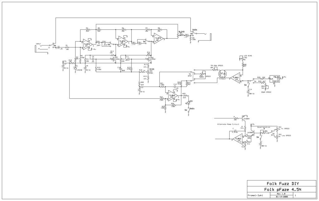

Image

Re: Folk pFaze 4.5%

PostPosted: Thu Jan 15, 2009 11:53 am
by cabo
Thanks Jfromel and Bjorn, Very cool of you guys to do this!

I like the idea of having an option(internal switch) to be buffered or bypassed. Not sure if that would make proper use of the extra op amp.?

and sorry I would not know the difference between the ramping circuits by looking at them...if possible maybe you could give a laymans explanation of what the difference is. 8)

please excuse my ignorance, my small electronic skills have been very limited but very excited to try and learn more from all this.

thanks again

Re: Folk pFaze 4.5%

PostPosted: Thu Jan 15, 2009 5:18 pm
by mills
Nice!

If not a buffer, I like the idea of an envelope option either for sweep, or to adjust speed or depth. I have wierd taste in modulation effects though, and that could just needlessly complicate things. Also, I think the phase 45 was pretty subtle, is it even wet enough to have an envelope wsweepo and be that noticible? No time to look at the ramp circuits yet, but I doubt I'd have anything more than a really basic understanding, so some explanation would be appreciated.

Do the phasing stages have to use 2 sides of an opamp, or could we do a swithchable extra stage for a little more effect, or is that enough to make a difference? I dunno... I've never looked much at phase shifters( until now).

And, thanks for the hard wortk guys!

Re: Folk pFaze 4.5%

PostPosted: Thu Jan 15, 2009 11:27 pm
by Donner
tone control might be a good option for that other op half ....

Re: Folk pFaze 4.5%

PostPosted: Thu Jan 15, 2009 11:29 pm
by Donner
Folk pFaze is endorsed by Garvis.

Image

Re: Folk pFaze 4.5%

PostPosted: Fri Jan 16, 2009 5:29 am
by jfromel
Bjorn suggested that I post our e-mails so you can see how we got where we did.......

Here is the back story to this project. The phase 45 is one of the most under rated effects out there IMO and has always been one of my favorites but like all the other stuff I build I thought, hrm I could do one better. Well I had a Lovepedal Vibe that was making a horrid pop when engaged so I opened it up to fix that - add a DC-tap and an LED, turns out that the Vibe is nothing more than a Phase 45 with the caps on positive side of the op-amps at 1:10 ratio instead of a 1:1, and that is what makes it VIBE. I also saw some ramping circuits on Keen's site that give a "Leslie" type effect. I thought combining them would be pretty nice and it wouldn't sound like a leslie, or a vibe, or a phaser but it would kind of sound like all of those things.

I thought this would make for a great folk project becuase there is so much that can be done with this circuit and we could all learn a lot.

Hi Bjorn,

>> Well here it is with the input and output and switching, etc, might
>> want to add some filtering to the 78L06, datasheet has a cap and
>> diode on P2 I think. I want to mess with the op-amps a bit as well,
>> could use a rail to rail like the TLC2262 or a TL062 for the LFO
>> and ramp then use TL072/OPA2134 for the rest, would still have ½ an
>> op-amp left to do something fun with, perhaps a tad of gain on the
>> loop with a 1n4001 or 1n34a to add some optional grit, not enough
>> to make it a drive pedal, just enough to mess it up a bit, perhaps
>> a single 1n34a with a 1n cap across on the feedback loop with 50KB
>> pot to adjust?
>>
> Hi,
>
> This took some time as I have had a very busy schedule but here goes
> on suggestions.
>
> Matching the FET's is a bit of work and 2N5458 may produce easily
> less than 20 useable in the circuit of a batch of 200 units so using
> the 2N5952 would give more units useable per a batch of 200
> transistors.
> I'd recommend a antilog potentiometer also for speed as in perhaps an
> Alpha 500KC.
> For switching caps with minimum noise a 47nF and 15nF cap could be
> wired in series for each allpass section and the 15nF caps shorted
> would give 47nF while series connection would give about 11nF's.
> I'd also suggest increasing C10 to about 68nF.
>
> Getting real hardcore DIY drilling out the LED part of the Vactrol
> and replacing the LED with a low current LED like the HPLMD-150 would
> take greater advantage of batterylife.
> A 1/4 inch drill would be needed for this and a very firm hand :).
> For the OP amps I'd suggest a TL062 for the Oscillator and led driver
> since those would draw low current and their noise preformance would
> not be an issue. On the Signal OP's it would be a tough question
> wether to choose those from overload handling or minumum
> noise........a number of devices could come to mind depending on
> desire.
>
> Yes bias could be used as a panel pot if the region is fixed meaning
> that this could mean a 50KB pot withR17 and R19 say 150K- some
> experimenting needed to spread the useful region over the pot travel.
>
> Maybe I have some more thoughts later
>
> Have fun
> BJ
>
> Well the idea between the switching caps at C2/C3 and C4/C5 is that
> when C2/C4 are engaged the ratio is 1:1 for phase when C3/C5 are engaged
> the ratio is 1:10 for a vibe effect. So it could be done with C2 at 47n
> with C4 and C5 in series at 100n ea (50n sum), then when switched add C3 at
> 1n2 in series with C2 (sum 9n5) and short C5 leaving only C4 (100n) and we
> get closer to 1:10 ratio. Tolerance is about 5% on spec.
>
> Also take a look at the alternate ramping circuit under the one
> that uses the Vactrol. It's easier to build but will it sound as good???? If
> going with the transistor ramp circuit U3 would need to be a rail to rail
> op-amp (LM2904 or TL2262)

Hi John,

Yes, I see what you'd like to do. I was only suggesting that the caps
would be wired in series and just one cap shorteded, since then any
switching noise would be eliminated.
Exact values could be made by parallelling if desired.
5% is good for this project- better tolerances would be overkill.

Hm, I wonder if not the alternate circuit could be more fun in use?

On rail to rail an LM358 could be used at low current draw and low cost.

Ah choices.

What do you think would this conversation be good and or educational
online?

Have fun

BJ

Well the two things I like about the alternate circuit is
1. The cost is much less - Those Vactrols are more than $5.00 us ea
2. I think it will be an easier circuit to get tuned up - those Vactrols have tighter tollerances than a CLM6000 but they are still not what I would call precise.

My concern is the log ramping may not sound very natural, to be honest when I look at the one with the Vactrol I can hear how it will sound but I am having a harder time hearing the other one. I have a couple of TL2272's here which are rail to rail so I might bread board these up and see what they sound like.

Can we use the LM358 for the LFO and the Ramp? I would like to keep those together.

I will send messages to Nick from NOC3 and some of the other builders who were in the Folk Fuzz 3.5% project.

Re: Folk pFaze 4.5%

PostPosted: Fri Jan 16, 2009 10:55 am
by DocRock
This is all quite fascinating, thanks for this. It is like Greek to me, unfortunately, as I don't even know how to read a schematic.

Still very, very cool though!!!

Doc 8)

Re: Folk pFaze 4.5%

PostPosted: Sat Jan 17, 2009 9:20 pm
by zion
YES! Yes! YES!

Re: Folk pFaze 4.5%

PostPosted: Sun Jan 18, 2009 12:54 am
by Blobcaster
Thanks guys!

Re: Folk pFaze 4.5%

PostPosted: Sun Jan 18, 2009 8:24 pm
by BJF
Hi,

Yes, it is easier to see how the Vactrol version would sound and yes I say sound comes first and is of biggest concern and I would agree with your concerns.
I think the log version has a few merits like you mention.
Come to think of it the vactrol version would be easier to faultfind having fewer parts allthough only just slightly so.

I would in view of this suggest then that we proceed on the first version using the Vactrol.
But by all means breadboard it and we'll see what it sounds like.
Yes the LM358 could be used in both the oscillator and the ramp. It's a low current, rail to rail dual OP.

A resistor at junction C1 SW is missing in the schematic and suggested value could be 1M

OK fine let them know.

On input notes

On depth of a Phase 45, yes that is less than the Phase 90 and I'd easily go for a 4 stage allpass filter possibly adding a resonance control, which would give ramping a more dramatic effect indeed.
This would involve more matching of J-FET's per pcb and might be a little to heavy also in view of Folk Fazing?
Two stages give one notch to be swept while four stages gives two notches to be swept. To get a deeper effect two more allpass filters would be called for.
A layout that uses something like Hammond 1590BB case would be easier to assemble, while either way this could be done in a smaller box.
I'll take a listen to an MXR Phase45 tomorrow to verify just how intense that is.

A switchable inputbuffer could be done, allthough for sake of number of amplifiers or rather IC's the circuit could also have it's amplifiers selected for their purposes:
U1 could be choosen NE5534 and in that case R3 choosen 1K1 and R4 1K0 while then a capacitor of 22pF would be required across pins 5 and 8 of the NE 5534 and that would end up being 3 IC's just the same.

More fun to come
BJ

Ahum endorsed by Garvis huh?
Check these guys wardrobes:
http://pics.yemii.com/swedish-dance-bands.html
Woohoo