Parts sourcing and component lists

A place for Do it Yourself projects

Moderator: Moderators

Re: Parts sourcing and component lists

Postby Corksniffer » Tue Oct 07, 2008 5:15 pm

Belt wrote:The easiest way for me to "make a triangle tranny socket" is to take a straight socket and cut the middle post out while leaving them in tact. Then place a single in the remaining hole.

It's kinda ghetto, but works without soldering your tranny's.


I dont believe these boards are large enough for that. You would have to solder in three separate pins without the ceramic/plastic insulation.
Corksniffer
 
Posts: 61
Joined: Sat Sep 13, 2008 4:10 pm

Re: Parts sourcing and component lists

Postby Belt » Mon Oct 13, 2008 5:12 pm

Having now populated my board, you are right.

It don't work. I soldered the tranny's... :cry:
Belt
 
Posts: 8
Joined: Wed Sep 10, 2008 2:34 pm

Re: Parts sourcing and component lists

Postby jfromel » Mon Oct 13, 2008 6:57 pm

If I ever do another run of these I will make the spacing for the trannies big enough for the can trannies.
Part time pedal builder with a day job now with a web site http://www.fromelelectronics.com
jfromel
 
Posts: 201
Joined: Sun Aug 10, 2008 3:02 pm

Re: Parts sourcing and component lists

Postby noelgrassy » Tue Oct 14, 2008 8:24 am

Corksniffer wrote:
Belt wrote:The easiest way for me to "make a triangle tranny socket" is to take a straight socket and cut the middle post out while leaving them in tact. Then place a single in the remaining hole.

It's kinda ghetto, but works without soldering your tranny's.


I dont believe these boards are large enough for that. You would have to solder in three separate pins without the ceramic/plastic insulation.


Well I stroked my board lovingly and I got mine in with the insulation intact at least on the 2 adjoining pins, the 3rd pin was inserted nekkid but it touches none of the others.
Sadly, I have these wee little Teflon sockets with gold pins that looked just perfect in terms of their "footprint". But as Murphy would have it the f*ckin' pin spacing is all wrong. :evil:

In the words of Lautremont,
"C'est la Vie"
Power Chords don't contain a third, so the maj&min qualities are not present. Heavy distortion adds harmonic content, and only perfect intervals have enough consonance to be clearly articulated at high distortion levels_DFunk
User avatar
noelgrassy
 
Posts: 39
Joined: Thu Aug 28, 2008 4:25 am
Location: Vaccuum Tube Valley

Re: Parts sourcing and component lists

Postby jfromel » Tue Oct 14, 2008 4:03 pm

The board is plated on both sides so you can always put your socket on the bottom side of the board. That is actually how I installed the germainiums on my folk fuzz.
Part time pedal builder with a day job now with a web site http://www.fromelelectronics.com
jfromel
 
Posts: 201
Joined: Sun Aug 10, 2008 3:02 pm

Re: Parts sourcing and component lists

Postby mrpicard » Sun Feb 22, 2009 11:16 pm

jfromel wrote:here is the BOM by Location. Remember that there are no hard and fast rules for this build. Bjorn has encouraged us to experiment with different values of caps, resistors, and trannies and the PCB layout that Nick at NOC3 put together allows for a few different types of clipping circuits....


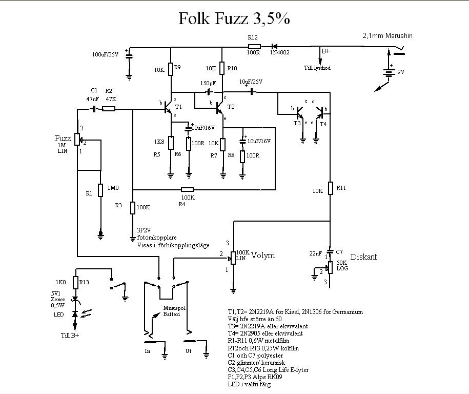
OK, I am a complete novice but I am willing to learn. What changes would I have to make to the circuit if I wanted to use OC76 germanium transistors in the Folk Fuzz 3,5% schema? I guess:

1. I guess these these would be used to replace the 2N1306 in T1 and T2? What about T3 and T4?
2. The 2N1306 transistors are NPN whereas the OC76s are PNP. Therefore, what changes should I make to the circuit to take this into account?
3. Would it be useful to have an internal trimmer to bias the OC76 transistors? If so, where is a good place to place these in the circuit?

If anyone says "why OC76 transistors" my reasons are:

1. I already have a "standard" Folk Fuzz 3,5% so I thought I would try something a bit different.
2. Thought I would see what "old school" is like.
3. I have some OC76 transistors so I might as well try.

Anyway, I hope answers to the above adds some more interesting knowledge to the Folk Fuzz story :-)

Regards, David

Image
User avatar
mrpicard
 
Posts: 306
Images: 377
Joined: Mon May 19, 2008 11:48 pm
Location: Sydney, Australia
pedals: 24

Re: Parts sourcing and component lists

Postby mills » Mon Feb 23, 2009 1:41 am

I'll let people with more experience answer the biasing questions, and I think that Bjorn has a comment or two in the modifications thread about a change or two for Ge transistors. For what its worth, I dropped some PNP's in while I had the circuit breadboarded and didn't adjust the biasing. I'm not sure if thats Bjorn designing an adaptable circuit that takes lots of transistors, or just a lucky pick with the PNP's I used.

I would think that you would only need to replace T1 and T2 with the OC76's. I'm pretty sure that T3 and T4 are using the transister as a diode to ground to clip the signal, and so there should be less (if any) advantage from using a Ge transistor.

To switch the circuit to PNP, you need to switch the polarity of the battery, and any polarized components (electrolytic capacitors, diodes, LED's). So, any of the capactors in that schematic with a plus sign (or one curved line) should be switched (100uf up top by the power supply, the two 10uF's off the emitter of T1 and T2, and the 10uF after T2). The 5.1V zener, LED, and 1N4002 would need to point in the other direction. There might be other ways to do this, but that's the easiest and the only one that I've done and can comment on. (it means that the pedal won't work on a daisy chain with other -ve ground effects though)

So, if you look at the great build photo tutorial, at step 3, D1 needs to be reversed. D2/3 and LED2/3 can stay the same way they already were since they're in pairs to the ground anyway. At step 6, the electrolytic capacitors need to be installed backwards. Step seven will be different for your particular transistors. Like it says, you'll have to look at the datasheet or somehow find which leg is the emitter, base, and collector. I think thats all for components, but the off board wiring will need to change a bit too.

With PNP's, i think that its easiest to use a positive ground, so the V+ connection on the PCB will connect to the -ve, and the Ground connection will connect to the +ve from the power supply. (I'm not sure if this helps you, but I always take a look at the General guitar gadgets PNP fuzzface to help with the wiring and schematics for +ve ground effects... the pictures of the components helps me get it sorted out).

http://www.generalguitargadgets.com/pdf/ggg_ff5_lo_pnp.pdf

Good luck! If I've managed jumbled anything up or left something out, someone with more experence should be abe to correct me pretty easily.
mills
 
Posts: 145
Joined: Thu Apr 24, 2008 10:28 pm
Location: Canada
Guitars:: Fender P/J Bass, Fender strat/tele hybrid
amps: 5e3 clone, solidstate bass head
pedals: 20

Re: Parts sourcing and component lists

Postby mrpicard » Mon Feb 23, 2009 5:22 pm

mills wrote:Good luck! If I've managed jumbled anything up or left something out, someone with more experence should be abe to correct me pretty easily.

Hi mills, thank you very much for that. That was an excellent explanation and I think I understand what to do now :-)
User avatar
mrpicard
 
Posts: 306
Images: 377
Joined: Mon May 19, 2008 11:48 pm
Location: Sydney, Australia
pedals: 24

Previous

Return to Folk Forum (DIY projects)

Who is online

Users browsing this forum: No registered users and 2 guests